Service hotline
+0086-139-2465-7372
In China's rapid prototyping industry, suppliers generally offer competitive manufacturing capabilities across various processes, with achievable tolerances aligning with international standards for prototype and low-volume production. Below is an overview of typical dimensional tolerances, flatness, and geometric tolerances for key processes provided by most Chinese suppliers.
Dimensional Tolerance:
Metals (Aluminum, Steel, etc.): ±0.05 mm to ±0.1 mm for standard parts; high-precision machining can achieve ±0.02 mm or tighter.
Plastics (ABS, PC, Nylon, etc.): ±0.1 mm to ±0.2 mm, influenced by material stability and part size.
Flatness: Typically 0.05 mm to 0.1 mm per 100 mm span for standard machining; can be improved to 0.02 mm with precision milling or grinding.
Geometric Tolerances (Parallelism, Perpendicularity, Circularity):
Parallelism/Perpendicularity: 0.05 mm to 0.1 mm per 100 mm.
Circularity (Roundness): 0.02 mm to 0.05 mm for holes or shafts.
Positional Tolerance: ±0.05 mm to ±0.1 mm for features like holes or pins.
Dimensional Tolerance: ±0.2 mm to ±0.5 mm, depending on part orientation, layer height, and calibration.
Flatness: Limited by layer adhesion and warping; typically 0.3 mm to 0.5 mm per 100 mm.
Geometric Tolerances: Generally lower due to layer stacking; parallelism/perpendicularity around 0.3 mm to 0.5 mm.
Dimensional Tolerance: ±0.1 mm to ±0.2 mm, with high-resolution printers achieving ±0.05 mm.
Flatness: 0.1 mm to 0.2 mm per 100 mm, influenced by resin shrinkage and support structures.
Geometric Tolerances: Parallelism/perpendicularity within 0.1 mm to 0.2 mm.
Dimensional Tolerance: ±0.2 mm to ±0.3 mm for nylon-based materials; shrinkage is a key factor.
Flatness: 0.2 mm to 0.4 mm per 100 mm.
Geometric Tolerances: Similar to dimensional tolerances, with positional accuracy around ±0.2 mm.
Dimensional Tolerance: ±0.2 mm per 100 mm, or ±0.1 mm for smaller parts (<100 mm). Total tolerance can reach ±0.3 mm to ±0.5 mm for larger parts (>500 mm).
Flatness: 0.2 mm to 0.3 mm per 100 mm, influenced by mold quality and casting process.
Geometric Tolerances:
Parallelism/Perpendicularity: 0.2 mm to 0.3 mm per 100 mm.
Positional Tolerance: ±0.2 mm to ±0.4 mm.
Note: Tolerances depend heavily on the master pattern (often CNC-machined or 3D-printed) and silicone mold stability.
Bend Angle Tolerance: ±1° to ±2° for standard bends; precision tooling can achieve ±0.5°.
Linear Dimension Tolerance: ±0.2 mm to ±0.5 mm for cut/flange dimensions.
Flatness (After Bending): 0.2 mm to 0.5 mm per 100 mm, depending on material thickness and tooling accuracy.
Geometric Tolerances:
Parallelism between bends: 0.3 mm to 0.5 mm per 100 mm.
Hole-to-bend position: ±0.2 mm to ±0.4 mm.
Standard vs. Precision Tolerances: Most suppliers quote "standard" tolerances (as above). Tighter tolerances are often achievable but may incur higher costs and longer lead times.
Material Influence: Plastics and resins generally have wider tolerances than metals due to thermal expansion, shrinkage, or flexibility.
Part Size Consideration: Tolerances are often scaled with part dimensions (e.g., ±0.1 mm per 100 mm).
Design for Manufacturing (DFM): Suppliers usually provide DFM feedback to optimize tolerances based on the selected process.
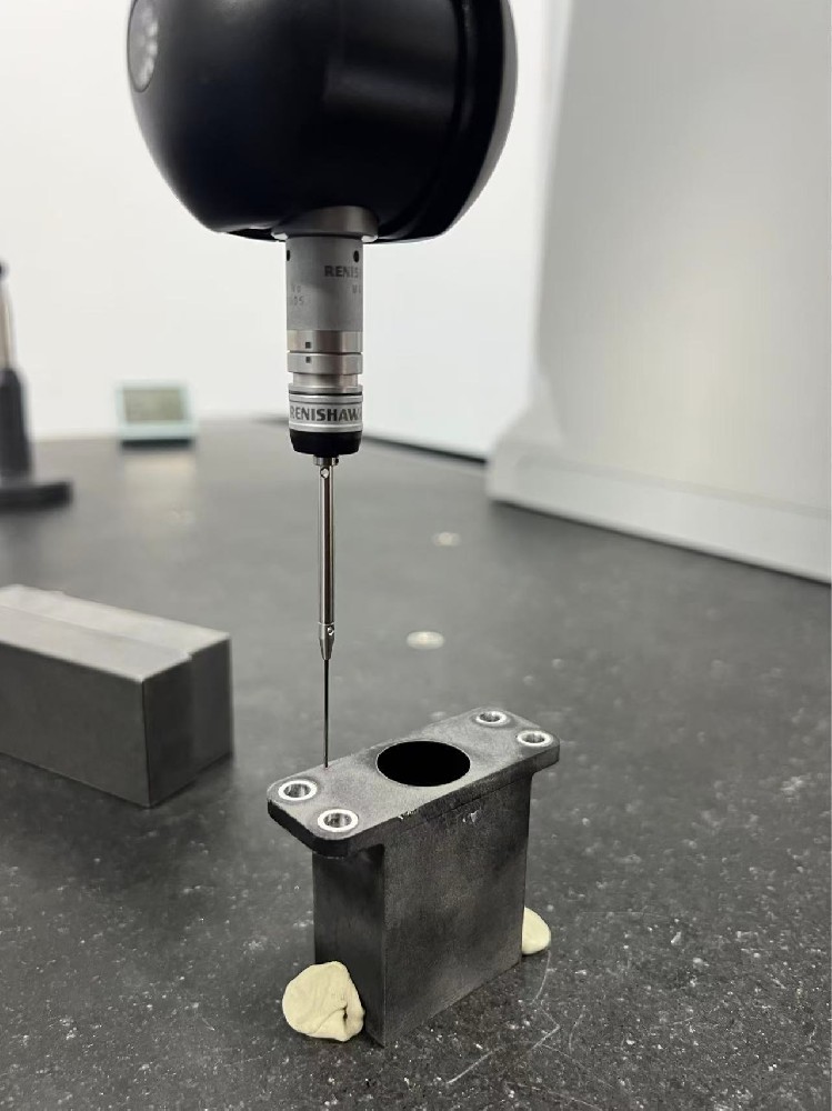
Quality Control: Leading suppliers use CMM (Coordinate Measuring Machine), laser scanners, and other inspection tools to verify critical tolerances.
| Process | Dimensional Tolerance | Flatness (per 100 mm) | Geometric Tolerance (Typical) |
|---|---|---|---|
| CNC Machining | ±0.05–0.1 mm | 0.05–0.1 mm | 0.05–0.1 mm |
| FDM 3D Printing | ±0.2–0.5 mm | 0.3–0.5 mm | 0.3–0.5 mm |
| SLA/DLP | ±0.1–0.2 mm | 0.1–0.2 mm | 0.1–0.2 mm |
| Vacuum Casting | ±0.2–0.3 mm | 0.2–0.3 mm | 0.2–0.3 mm |
| Sheet Metal Bending | ±0.2–0.5 mm | 0.2–0.5 mm | 0.3–0.5 mm |
For precise requirements, it is recommended to:
Specify critical tolerances on drawings and discuss them with the supplier early.
Request inspection reports for critical dimensions.
Consider prototyping before full production to validate tolerances.